

Burckhardt Compression is one of the world's largest manufacturers of reciprocating compressors with more 40 years of experience in offshore applications.
Hamworthy Oil & Gas Systems, which will soon be part of Finland's Wartsila after a takeover, is a leading supplier of cargo-handling technology and systems liquefying boil-off gases (BOG) from LNG carriers.
Burckhardt and Hamworthy have cooperated to develop a complete concept for handling BOG and injecting natural gas into the dual-fuel, two-stroke engines from MAN Diesel (ME-GI) of Germany.
Combination
The combination of reliquefaction with dual-fuel engines offers a flexible system which makes it possible to switch between fuels - depending on fuel prices.
The engines are efficient and not all BOG can be utilized in the engine in the different operating modes. Rather than burning excessive gas in the gas combustion unit, the gas can be liquefied and returned to the tanks.
The advantages are:
- Flexible fuel system
- Optimized fuel cost
- Increased cargo quantity delivered
- More profitable freight contracts
The following requirements have been identified during the development of the compression system for successful and easy integration with the other systems on the ship, such as engines,
The BOG reliquefaction, auxiliary power requirements and tank design need compression from atmospheric pressure to 300 bar with discharge pressure varying between 150 to 300 bar; temperature range at inlet is from -160°C to 45°C and discharge temperature is a maximum 45°C.
 |
|
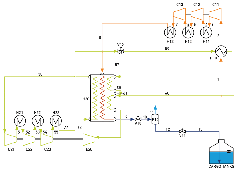
Figure 1: Process illustration of BOG Reliquefaction System (Mark III) |
Side streams
There is also the possibility of extracting side streams for reliquefaction and auxiliary gas engines, and flexible throughput control to efficiently meet system requirements at base and part load.
In addition, the system means reduced vibration induced on the ship/tank structure, less space requirements (vertical compressor design advantageous) and simple installation.
The system also offers availability in the high 90 percent, MTBO 20,000 hours or higher, easy maintenance, preferably carried out by on-board engineers, and the optimization of investment and operating costs.
We will look in this article at the high-pressure compressor combined with BOG reliquefaction system (LNG RS).
BOG reliquefaction systems are being optimized due to the demand for better solutions with less power consumption. New types of systems with improved efficiency and less space requirements have been introduced.
Savings
A series of LNG carriers have been constructed using reliquefaction and the Hamworthy system. Significant savings can be achieved by using duel-fuel propulsion and selling excessive reliquefied BOG.
Unlike all other cargo ships LNG carriers have - until recently - used only steam turbine propulsion plants despite more efficient two-stroke engines or DFDE engines being available.
This was because the gas that naturally evaporates from the cargo (BOG) was used as fuel for the steam turbines, and no other alternative could have been provided.
The ability to reliquefy BOG makes it possible to increase the amount of LNG delivered to the terminal, which is more profitable than using it as fuel.
For the new LNG carriers being delivered, the cost reduction may typically be $5 million a year. Reliquefaction plants have been used for many years on liquefied petroleum gas (LPG) carriers.
History
Cargoes, such as butane and ethylene, are kept liquid below their boiling points, and boil-off gases are returned to the cargo tanks by reliquefaction systems that have been supplied by Hamworthy for more than 40 years.
The Hamworthy first generation of BOG reliquefaction system is referred to as Mark I, and utilizes cryogenic BOG compression for controlling the cargo tank pressure.
The latest generation BOG reliquefaction system (LNG RS) is Mark III which is installed on 11 of the Q-FLEX vessels operated by Qatar.
The incentive for developing new generations of LNG RS was to make more cost efficient systems, continue to be market leader and be innovative.
Compared to the Mark I design, Mark III represents a considerable benefit in terms of energy savings - typical 15-20 percent. The given power reduction is both documented theoretically - by simulations - but also through evaluation of power consumption of the LNG RS on the Q-Flex vessels.
Reduced power
The main reason for the reduced power is that cold duty in the BOG is utilised in the preheater and also, the heat of compression is rejected through cooling water in the intercoolers and after-cooler.
Power savings in this range will also represent positive synergy effects with respect to power related equipment. Electrical motors, frequency converters, and power generators may be significantly reduced as a result of the more efficient process.
Reliquefaction is based on a closed nitrogen cycle extracting heat from the BOG.
Several novel features such as separation and removal of incondensable components have resulted in a compact system with low power consumption.
A BOG reliquefaction system in combination with two-stroke propulsion has both economic and technical advantages.
The principle for the Mark III BOG reliquefaction system is that the BOG with vapour header temperature is pre-heated up to near ambient temperature in a heat exchanger upstream the BOG compressor.
 |
|
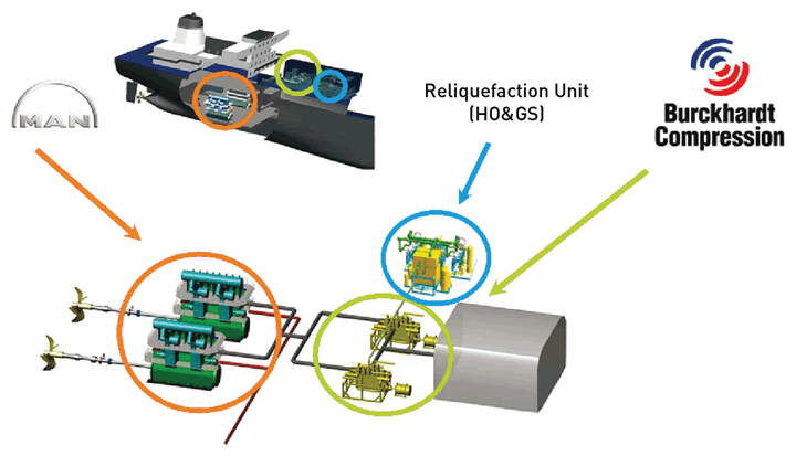
Figure 2: ME-GI and Laby-GI combined with reliquefaction on a carrier |
Process
The BOG is pre-heated in heat exchanging with the high-pressure nitrogen stream taken downstream the nitrogen compander after-cooler.
The result is no requirement for cryogenic materials. The BOG is evacuated from the LNG tanks by a three-stage centrifugal type BOG-compressor with subsequent cooling after each stage.
Alternatively this can be changed to a reciprocating compressor supplied by BC. This configuration ensures that the heat of compression can be rejected through cooling water in the coolers.
The Mark III system with pre-eater and ambient BOG compression has its patent pending.
Downstream the BOG-compressor the vapour is cooled and liquefied at this pressure to about -160°C in a cryogenic plate-fin heat exchanger. This ensures condensation of hydrocarbons to LNG.
Feature
A special feature of the Hamworthy reliquefaction process is that not all the nitrogen in the BOG is condensed at -160°C for LNG with higher content of nitrogen.
As for Mark I, nitrogen gas is compressed in a compander unit (three-stage centrifugal compressor and single expander on a common gear box).
After the third stage cooler the stream is split into two different streams. One stream is used to pre-heat the BOG in a separate heat exchanger (pre-heater) and the other is led to the "warm" part of the cryogenic heat exchanger.
After heating the BOG, the two streams are mixed together again, and reintroduced into the cold box core. In the cryogenic heat exchanger nitrogen is pre-cooled and expanded to almost compressor suction pressure.
It leaves the expander at temperature below -160°C and is returned to the "cold" part of the cryogenic heat exchanger. The cold nitrogen continues through the "warm" part of the cryogenic heat exchanger.
Compressor
The compression of cryogenic BOG up to discharge pressures in the range of 10-50 bar is nowadays common practice in many LNG production and receiving terminals worldwide.
Compressor designs employ the highly reliable labyrinth sealing principle which is extensively used for such applications.
Burckhardt compression has many decades of experience with process gas compressors according API 618 guidelines with discharge pressure to 550 bar. This type of compressor uses ring seals on piston and piston rod.
In the development of the Laby®-GI the main challenge was to integrate the two sealing systems (labyrinth sealing and ring sealing) in a single compressor in an efficient and reliable manner to meet the requirements of the ME-GI dual-fuel engine.
The development of the Laby-GI compressor started in 2004 with the close cooperation between Burckhardt and MAN Diesel & Turbo.
Flexibility
In the last three years or so more flexibility has been achieved with the introduction of a parallel reliquefaction system in conjunction with two-stroke MEGI engines.
Without doubts this gives full flexibility to the operator to burn or reliquefy the LNG BOG.
The unique compressor design allows the selection of the best applicable cylinder sealing system according to the individual stage operating temperature and pressure.
In this way, very high reliability and availability with low maintenance is achieved. With the gas-tight crankcase design there is no gas loss to the environment and no need for purge and buffer gas. This makes the Laby-GI also one of the safest available systems.
The double-acting and oil-free labyrinth compression stages, required for very cold low-pressure stages one to three, are typically found at LNG receiving terminals.
 |
|
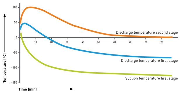
Figure 3: The cool-down process of the Laby LNG compressor |
Friction
The avoidance of mechanical friction in the contactless labyrinth cylinder, results in an extremely long lifetime for the sealing components.
The Laby-GI is designed to deliver low-temperature BOG (natural or forced) from atmospheric tank pressure up to gas injection pressure in the range of 150 to 300 bar.
The proven labyrinth sealing system of the Laby permits cryogenic compressors to start-up and operate at ambient suction conditions without any pre-cooling procedure.
This means that continuous operation of the compressor can be achieved without any restriction to discharge pressure requirements. Fast start-up and shut-down are key benefits of this system.
For the Mark III reliquefaction system which uses the BOG as a heat sink in a heat exchanger (pre-heater) installed in the compressor suction line, the compressor suction temperature is usually above 0°C.
In case of no operation of the reliquefaction system, the compressor can immediately be operated with the cold BOG from the tank. The change from cryogenic to ambient suction temperature is equally simple.
 |
|
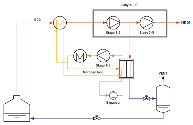
Figure 4: Flow diagram of the integration between LNG RS and Laby-GI |
Turndown
Importantly too, stepless turndown is required by the ME-GI engine. This is achieved by combining valve unloading and three different bypasses.
With this conventional arrangement, frequently used for reciprocating compressors, efficient turndown to 0 percent capacity is achieved.
The compressor package's overall dimensions for marine applications are strictly relying on the restricted space available, such as within a deck-mounted machinery room.
The vertical design of the Laby-GI optimizes the required footprint on deck compared to horizontal reciprocating compressors.
In addition, such an arrangement poses strict limits on the allowable vibration. The design employs a modular assembly whereby the three modules are prefabricated and aligned before installation on the LNG carrier.
Fuel-gas
Hamworthy and Burckhardt have jointly developed a solution where the Laby-GI fuel-gas compressor is integrated with the BOG reliquefaction system. The Laby-GI will replace the conventional BOG compressor upstream the reliquefaction plant.
Two fuel-gas compressors are installed. Each is designed to supply the ME-GI engines at maximum continuous rating (MCR).
A typical arrangement is with 1 x 100% reliquefaction capacity and 2 x 100 percent capacity for the Burckhardt compressors. The reliquefaction plant can be designed for full or reduced capacity.
The design suction pressure was chosen relatively low at 1.03 bara. The compressor model used for all studied gas compositions is a six-crank, six-cylinder, fully-balanced 6LP250-5 S-1.
As for Mark III reliquefaction, a heat exchanger (pre-heater) is installed in the compressor suction line.
Cases
The given heat exchanger increases the inlet temperature to the compressor to ambient temperature in operating cases with excess BOG. In cases without excess BOG - when the reliquefaction unit is not running - inlet gas is not warmed up, and thus an inlet temperature of -140°C is taken into consideration.
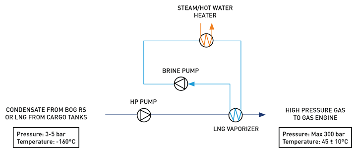
Compression takes place in five stages. Bypasses are installed over stage 1 - from stage 3 back to the suction line, and from stage 5 to the inlet of stage 4. Also the bypasses allow efficient turn-down.
 |
|
Figure 5: The illustrated compressor flow chart |
The side stream for the reliquefaction unit to liquefy excess BOG is taken downstream at second-stage intercooler at around 16 bar (alternatively 1st stage and 5 bara). BOG can be partly - or fully - diverted to the reliquefaction system. The remaining gas will be compressed in the last 3 compressor stages before it is injected into the engine.
If the ME-GI engine is running in gas mode (fully or partly), the required BOG is sent directly from the compressor to the engine, thereby by-passing the reliquefaction system. If any, excessive gas is liquefied in the reliquefaction mode.
Alternatively the engine is running in HFO (heavy fuel oil) mode and the BOG is liquefied in the reliquefaction plant. In ballast voyage the operator can choose to run the vessel on HFO and liquefying the BOG to keep the cargo tanks cold or utilize the BOG for fuelling the engine.
In several operating cases the amount of natural BOG is lower than the gas flow required by the engine. In these cases additional, vaporized LNG is introduced upstream of stage 2 at about -70°C and 5 bara.
By using vaporized LNG the use of HFO can be reduced drastically. This system allows efficient compressor operation in the following cases:
• Operation with excess BOG with reliquefaction unit running and warm compressor inlet temperature
• Engines stopped, all BOG is sent to the reliquefaction unit, warm inlet temperature
• Any ratio of gas sent to the reliquefaction unit or to the engines, warm inlet temperature
• All gas sent to the engines, reliquefaction unit switched off, cryogenic inlet temperature
• Operation with natural BOG and vaporized LNG with cryogenic inlet temperature
Pump system
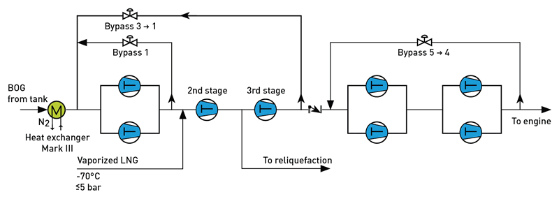
Condensate from the BOG reliquefaction system, or LNG from the cargo tanks, is supplied by the cargo pumps and sent to the fuel-gas supply system. Typically, this system consists of a booster pump, high-pressure pump and a heating system.
LNG is pumped above super-critical pressure and heated to the required temperature in the LNG vaporizer (heat exchanger).
Subsequently, the high-pressure gas is further fed to the dual-fuel engine. The discharge pressure of the high-pressure pump is typically 300 bar at design case.
Evaporation of LNG at high pressure is based on an intermediate brine loop. Engine jacket water, steam or process water are normally used as heating medium. Also, in order not to use jacket water or steam from the machine room directly against LNG, a closed brine loop is used to heat the LNG.
The brine or intermediate media, is often a "brine" mixture, glycol mixture or even a refrigerant. Process water will have lower inlet temperature and direct heat exchanging should be considered instead of an intermediate loop.
LNG at typically -160 degrees C and approximately 5 bar is pressurized in a cryogenic multi-head reciprocating pump (HP pump) to 300 bar. The LNG is then evaporated and heated to typically ambient temperature in a heat exchanger.
The configuration will typically be 2x100 percent capacity for rotating equipment - one in operation and one in standby. It is assumed that the gas-supply system will be installed in the cargo compressor room together with the BOG reliquefaction plant.
 |
|
Figure 6: Gas-supply system with HP pump, vaporization system and closed intermediate loop. LNG from the cargo tanks, is supplied by the cargo pumps |
Conclusion
The installation of BOG reliquefaction capacity on dual-fuel LNG carriers provides ship operators with flexibility to switch between fuels - depending on the relative cost of LNG and heavy fuel oil.
Propulsion systems are efficient and not all the BOG can be utilized in the engine. Slow speed sailing and ship holding operations often result in excessive BOG.
Rather than burning BOG in a gas combustion unit, it can be reliquefied and returned to the cargo tanks. The advantages are extremely attractive with a flexible fuel system, optimized operating costs and increased delivered cargo capacity.
Cooperation between Hamworthy and Burckhardt has resulted in the development of a complete concept for handling BOG on ships powered by MAN Diesel's two-stroke dual-fuel ME-GI engine.
The highly efficient Mark III nitrogen based reversed Brayton cycle reliquefaction system by Hamworthy is augmented by the high-pressure Laby-GI from Burckhardt.
The gas-handling system comprises high-pressure injection into the ME-GI engine and the reliquefaction of excess boil-off gas taken from a side stream of the Laby-GI compressor.
During a ballast voyage, the system offers flexibility to burn or reliquefy the amount of BOG available, or HFO can be used.
Different concepts to integrate the BOG reliquefaction system with the gas-injection systems to the ME-GI engine are evaluated and compared.
The graphs show that the combination of Burckhardt compressor with LNG RS has lower power consumption than the LNG pump solution.
For an engine load in the range of 75 percent to 100 percent the difference in power consumption between pump (optimizer) and the compressor concept is about 14 percent. Without the optimizer the difference is about 25-30 percent.
In addition to power consumption a complete evaluation of the concepts must include capital expenditure, footprint, overall dimensions, installation, integration, availability and maintenance.
Martin Fux, Burckhardt Compression, and Eirik Melaaen of Hamworthy Oil & Gas
This article is based on extracts from a paper entitled "Reliquefy or burn as fuelgas approach to BOG handling on LNG carriers with DF ME-GI propulsion"